Use Case Diagrams: Functional Requirement Modeling
1. Overview and Purpose
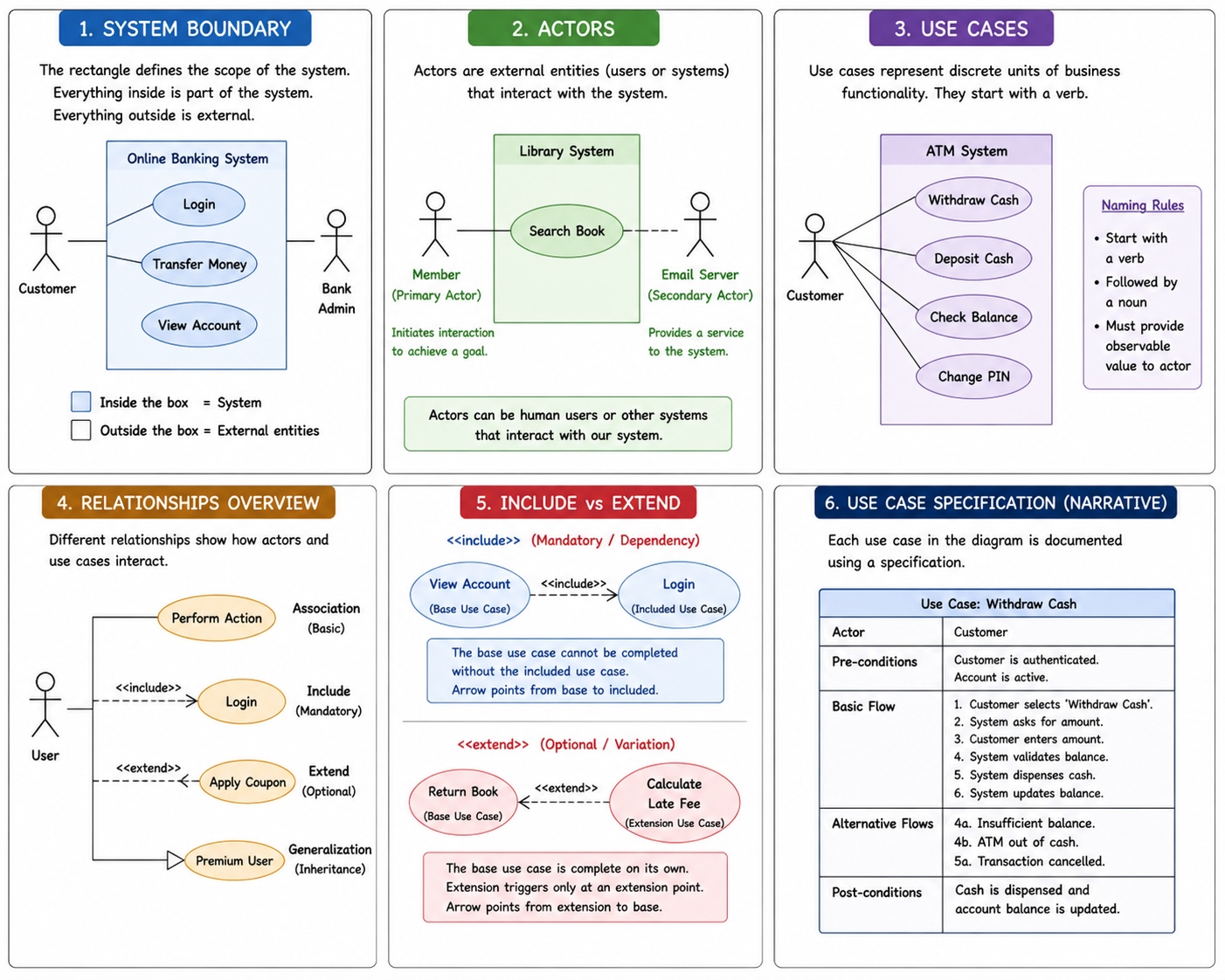
A Use Case Diagram is a behavioral UML diagram that describes a set of actions (Use Cases) performed by a system in collaboration with one or more external users (Actors). It serves as a high-level visual representation of a system's functional requirements.
- Primary Purpose: To help stakeholders and development teams visualize the functional requirements, the scope of the system, and the relationships between actors and essential processes.
- User Perspective: It answers "What does the system do?" from the user's point of view.
- Scoping: It defines the system's "Black Box" behavior. By identifying what is inside the diagram, it simultaneously clarifies the system's boundaries and defines what the system will NOT do.
2. Core Components
System Boundary
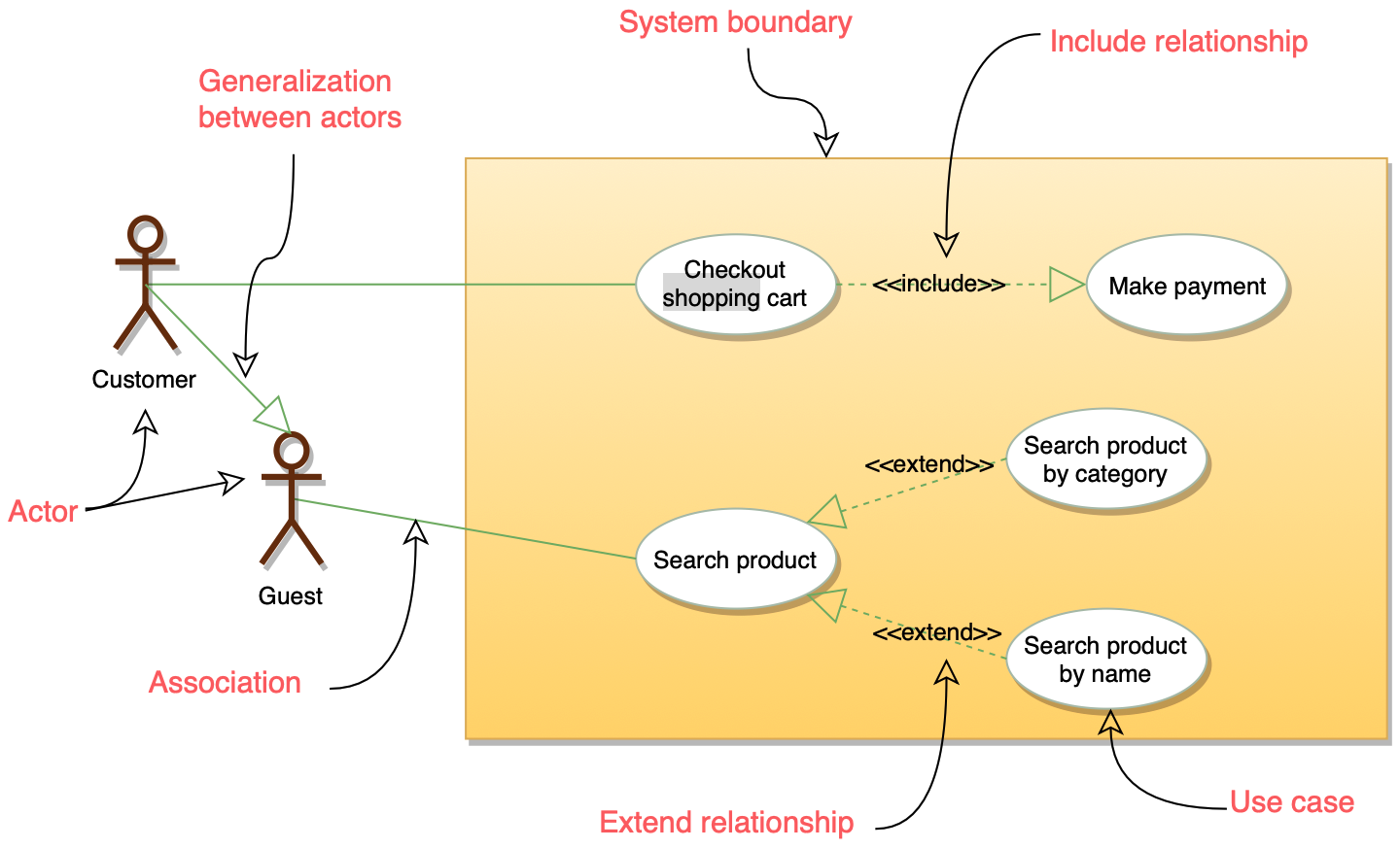
Represented by a rectangle enclosing the use cases. It defines the scope of the system. Anything inside the box is part of the system being developed; anything outside is an external entity.
Actors
Represented by a stick figure. An actor represents a role played by a user or another system that interacts with the subject.
- Primary Actors: Usually placed on the left. They initiate the interaction to achieve a goal.
- Secondary/Supporting Actors: Usually placed on the right. They provide a service to the system (e.g., a Database, an Email Server, or a Payment Gateway).
Use Cases
Represented by an oval. A use case represents a discrete unit of business functionality.
- Naming Convention: Must start with a verb followed by a noun (e.g.,
Withdraw Cash,Generate Report). - Observable Result: Every use case must provide a measurable value to an actor.
3. Relationships
Relationships define how actors and use cases interact.
| Relationship | Type | Description |
|---|---|---|
| Association | Basic | A solid line connecting an actor to a use case. Indicates that the actor participates in the use case. |
| Include | Mandatory | A dashed arrow with the <<include>> stereotype. Indicates that the base use case requires the functionality of another (e.g., Login is included in View Account). |
| Extend | Optional | A dashed arrow with the <<extend>> stereotype. Indicates a use case that adds behavior to a base use case under specific conditions (e.g., Calculate Late Fee extends Return Book). |
| Generalization | Inheritance | A solid line with a hollow arrowhead. Used when a use case or actor is a specialized version of another (e.g., Credit Card Payment is a specialization of Make Payment). |
4. Relationship Details: Include vs. Extend
In modern design, the direction of the arrow and the "base" logic are the most frequent points of confusion:
<<include>>(Dependency): The base use case cannot be completed without the included one. The arrow points from the base to the included use case. It is used for extracting common parts of behaviors.<<extend>>(Variation): The base use case is complete on its own. The extension only triggers at a defined Extension Point. The arrow points from the extension to the base use case.
5. Use Case Specification (The Narrative)
A diagram alone is rarely enough. In a professional setting, each use case in the diagram is backed by a Use Case Specification document containing:
- Actor: Who is involved.
- Pre-conditions: What must be true before the use case starts.
- Basic Flow (Happy Path): The standard successful sequence of events.
- Alternative Flows: Deviations from the happy path.
- Post-conditions: The state of the system after execution.
6. Modern Perspective: Use Cases vs. User Stories
In current Agile (2026) environments, developers often debate Use Cases vs. User Stories:
- User Stories focus on the "Why" and the value (
As a..., I want..., So that...). They are intended for quick iteration. - Use Cases focus on the "What" and the "How" (interaction steps). They are better for complex systems where detailed requirements and edge cases must be mapped out early.