UML Sequence Diagrams: Modeling Dynamic Interactions
1. Overview
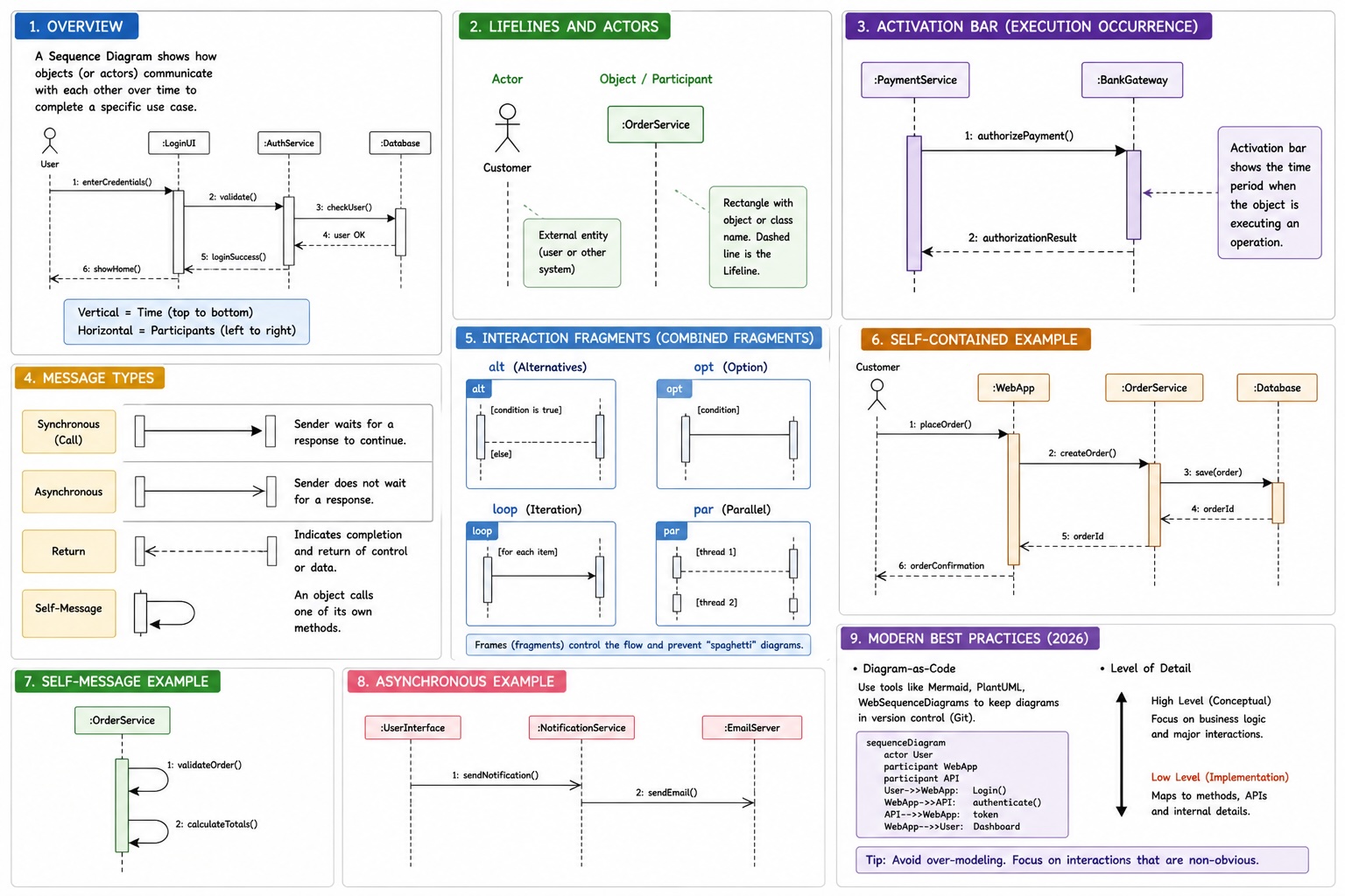
A Sequence Diagram is an interaction diagram that illustrates how objects communicate in a specific order over time. It provides a detailed, step-by-step flow of a specific use case or a sub-process within a system.
- Primary Focus: The chronological order of messages.
- Scope: Often used to model the logic of a single use case, a specific method implementation, or an API request-response cycle.
- Clarity: While often described as "self-explanatory," their power lies in their ability to visualize complex logic that would be difficult to follow in raw code.
2. Dimensions of a Sequence Diagram
A sequence diagram is mapped onto a 2D grid:
- The Vertical Dimension (Time): Represents the passage of time from top to bottom. Messages placed lower on the diagram occur after those placed higher.
- The Horizontal Dimension (Participants): Represents the different Lifelines (Actors or Object Instances) involved in the interaction.
3. Core Components
Lifelines and Actors
- Actors: Represented by a stick figure; these are external entities (users or other systems) initiating the sequence.
- Objects/Participants: Represented by a rectangle containing the object and/or class name. A dashed vertical line (the Lifeline) extends downward from the participant.
Activation Bars (Execution Occurrences)
Represented by a thin rectangle on top of a lifeline. It indicates the period during which an object is performing an operation or is "active."
Message Types
Messages are the arrows that carry information between lifelines.
| Message Type | Notation | Description |
|---|---|---|
| Synchronous | Solid line + Filled Arrow | The sender waits for a response before continuing. |
| Asynchronous | Solid line + Open Arrow | The sender continues without waiting for a response (common in event-driven systems). |
| Return | Dashed line + Open Arrow | Indicates the completion of a task and the return of control/data to the caller. |
| Self-Message | U-turn Arrow | An object calling one of its own methods. |
4. Interaction Fragments (Combined Fragments)
In modern UML (2.x), we use Frames to represent logic like loops and conditionals. This prevents the diagram from becoming a messy "spaghetti" of arrows.
| Fragment | Meaning | Usage |
|---|---|---|
alt | Alternatives | Models "If-Then-Else" logic. Only one operand executes. |
opt | Option | Models "If" logic. The sequence inside happens only if a condition is met. |
loop | Iteration | Models "For" or "While" logic. The sequence repeats. |
par | Parallel | Logic that happens simultaneously across different lifelines. |
5. Modern Best Practices (2026)
Diagram-as-Code
Rather than drawing these manually, current industry standards prefer using Diagram-as-Code tools like Mermaid.js, PlantUML, or WebSequenceDiagrams. This allows sequence diagrams to be version-controlled in Git alongside the source code.
Level of Detail
- Conceptual Level: Focus on high-level business logic.
- Implementation Level: Map directly to class methods and API endpoints.
Tip: Avoid over-modeling. If a sequence diagram looks like a literal translation of the code, it may be too detailed. Focus on the interactions that are non-obvious.