UML Class Diagrams: Static Structure Modeling
1. Overview
A Class Diagram is a structural UML diagram that describes the static structure of a system. It shows the classes, their attributes, operations (methods), and the relationships among objects.
- Code Mapping: It is the only UML diagram that can be mapped directly to object-oriented (OO) languages (Java, C#, C++, etc.), making it the "blueprints" for software construction.
- Purpose: To visualize the data model and the functional capabilities of the system's components.
2. Class Representation
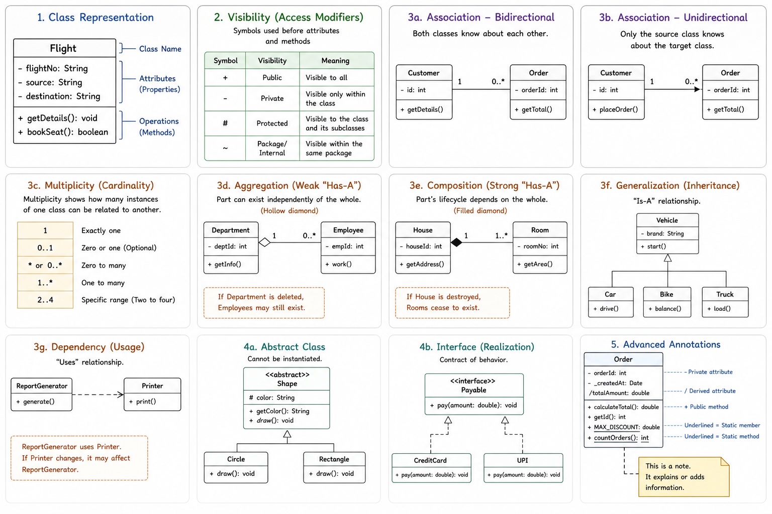
A class is depicted as a rectangle divided into three horizontal sections:
- Top Section: The class name (e.g.,
Flight). It should be bold and centered. - Middle Section: The class properties/attributes (data).
- Lower Section: The class operations/methods (functionality).
Visibility (Access Modifiers)
In modern standards, you must denote the visibility of attributes and methods using these symbols:
+: Public (Visible to all)-: Private (Visible only within the class)#: Protected (Visible to the class and its subclasses)~: Package/Internal (Visible within the same package)
3. Relationships and Navigation
Relationships define how classes interact and hold references to one another.
Association
A solid line representing a structural link between two classes.
- Bidirectional: A simple solid line. Both classes are aware of each other.
- Unidirectional: A solid line with an open arrow. Only the "source" class knows about the "target."
Multiplicity (Cardinality)
Multiplicity specifies the range of permitted instances that can participate in a relationship.
| Multiplicity | Meaning |
|---|---|
1 | Exactly one |
0..1 | Zero or one (Optional) |
* or 0..* | Zero to many |
1..* | One to many |
2..4 | Specific range (Two to four) |
Aggregation vs. Composition
Both model a "Whole-to-Part" relationship, but their lifecycles differ significantly.
- Aggregation (Weak "Has-A"): Denoted by a hollow diamond at the "whole" end. The part can exist independently of the whole (e.g., a Library and its Books). If the Library is deleted, the Books remain.
- Composition (Strong "Has-A"): Denoted by a filled (black) diamond at the "whole" end. The part’s lifecycle is tied to the whole (e.g., a Room in a House). If the House is destroyed, the Rooms cease to exist.
Generalization (Inheritance)
Denoted by a solid line with a hollow triangular arrowhead pointing to the superclass. This represents an "Is-A" relationship where a subclass inherits the state and behavior of a parent class.
Dependency (Usage)
Denoted by a dashed line with an open arrowhead. It represents a "Uses" relationship. If the supplier class changes, the client class may be affected (e.g., a class using another as a temporary local variable or parameter).
4. Interfaces and Abstract Classes
Abstract Classes
Identified by italicizing the class name or adding the <<abstract>> stereotype. Abstract classes cannot be instantiated.
Interfaces
An interface defines a contract of behavior. Interfaces are implemented using Realization.
- Notation: A dashed line with a hollow triangular arrowhead (Realization) or the "lollipop" notation.
- Stereotype: The name is usually preceded by
<<interface>>.
5. Advanced Annotations
- Static Members: To denote a static attribute or method (one that belongs to the class itself rather than an instance), the text is underlined.
- Derived Attributes: An attribute that can be calculated from other attributes (like
agefrombirthDate) is prefixed with a forward slash (/age). - Notes/Comments: Represented as a rectangle with a folded corner, connected to the relevant class by a dashed line.